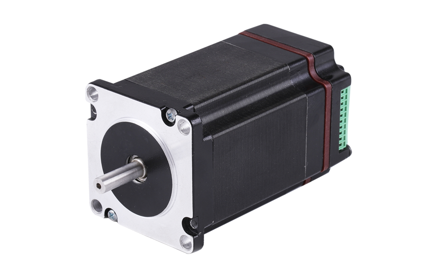
IO57
- Manual Quote
| Item | (Specifications) |
|---|---|
| Step Angle | 1.8。 |
| Step Angle Accuracy | ±5% ( ) |
| Radial Play | 0.02mm@450 g |
| Axial Play | 0.08mm@450 g |
| Max. radial force | 75N @ 20 mm from the flange |
| Max. axial force | 15N |
| Dielectric Strength | 600VAC / 1S |
| Insulation Resistance | 100MΩ ,500VDC |
| Ambient Temperature | -20。C~+50。C |
| Insulation Class | Class B |
| IO57-10· Phase current | 2.8 |
| IO57-10· Resistance | 0.9 |
| IO57-10· Inductance | 2.5 |
| IO57-10·Holding torque | 1.26 |
| IO57-10·Detent torque | 0.04 |
| IO57-10· | 4 |
| IO57-10·Rotor inertia | 300 |
| IO57-10·Weight | 0.9 |
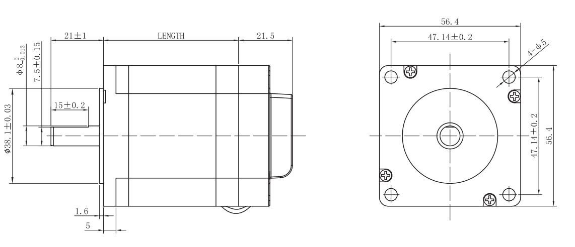
| IO57-10· Length | 54±1 |
| IO57-22· Phase current | 5.6 |
| IO57-22· Resistance | 0.4 |
| IO57-22· Inductance | 1.8 |
| IO57-22·Holding torque | 2.2 |
| IO57-22·Detent torque | 0.07 |
| IO57-22· | 4 |
| IO57-22·Rotor inertia | 500 |
| IO57-22·Weight | 1.5 |
| IO57-22· Length | 80±1 |
| Specifications | (Unit) |
| InputVoltage / Input voltage (DC) | 20 | 36 | 50 | Vdc |
| OutputCurrent(Peak)/ Output current (peak) | 1.5 | - | 5.6 | A |
| Pulse / Step pulse frequency | 0 | - | 200 | KHz |
| PulseVoltage/ Pulse voltage | - | 5 | - | Vdc |
| ControlSignalInputCurrent/ Control signal input current | 7 | 10 | 16 | mA |
| Resistance/ Insulation resistance | 100 | - | - | MΩ |
| Pin description | (Function) |
| +Vdc | 。 Power supply, 20~50 Vdc, Including voltage fluctuation and EMF voltage. |
| GND | (Power Ground) |
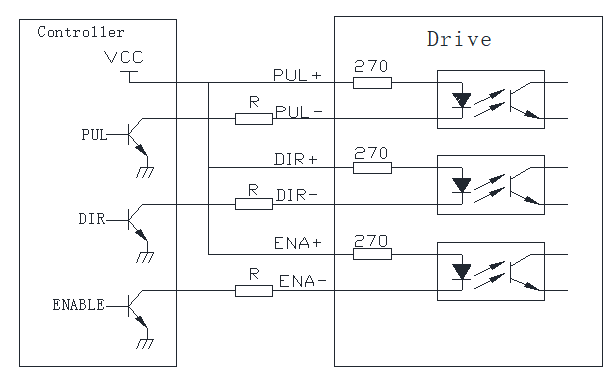
| PUL+(+5V) | ;PUL- 0~0.5V。 +12V or +24V 。 Pulse control signal: pulse rising edge is valid; PUL-high level is 4~5V, low level is 0~0.5V. In order to respond reliably to pulse signals, the pulse width should be greater than 2.5. If +12V or +24V is used, string resistance is required. |
| DIR+(+5V) | / 5μs 。 A+、A- ,DIR- 0~0.5V。 Direction signal: High/low level signal. To ensure reliable commutation of the motor, the direction signal should be established before the pulse signal is at least 5μs. The initial running direction of the motor is related to the wiring of the motor. Interchanging any phase winding (such as A+, A-exchange) can change the direction of the initial running of the motor, DIR-high level 4~5V, low level 0~0.5V. |
| ENA+(+5V) | Enable signal: this input is used to enable or disable the driver. When ENA+ is connected to +5 V and ENA- to low level (or the internal optocoupler conducts), the driver cuts off the motor phase currents and the motor becomes free; step pulses are not responded to. If this function is not needed, leave the enable terminal floating. |
| Pin | (Function description) |
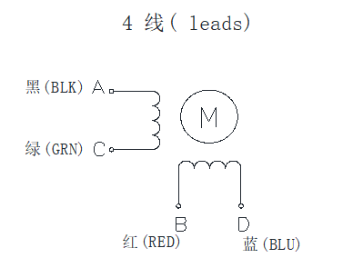
| A+ | Motor phase A+ |
| A- | Motor phase A- |
| B+ | Motor phase B+ |
| B- | Motor phase B- |
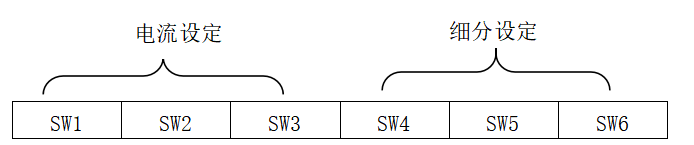
| OutputPeakCurrent Peak Current | RMS Current | SW1 | SW2 | SW3 |
| Default 1.5A【PK】 | oN | oN | oN |
| 2.1A | 1.5A | oFF | oN | oN |
| 2.7A | 1.9A | oN | oFF | oN |
| 3.2A | 2.3A | oFF | oFF | oN |
| 3.8A | 2.7A | oN | oN | oFF |
| 4.3A | 3.1A | oFF | oN | oFF |
| 4.9A | 3.5A | oN | oFF | oFF |
| 5.6A | 4.0A | oFF | oFF | OFF |
| / 1.8°motor) Steps/rev. (for 1.8°motor) | SW4 | SW5 | SW6 |
| Default(400) | ON | ON | ON |
| 800 | OFF | ON | ON |
| 1600 | ON | OFF | ON |
| 3200 | OFF | OFF | ON |
| 4000 | ON | ON | OFF |
| 5000 | OFF | ON | OFF |
| 6400 | ON | OFF | OFF |
| 12800 | OFF | OFF | OFF |
Description
Product Center Built-in Driver
Dynamic Current Setting
This motor can be customized to meet customer requirements.
Note: when VCC is 5 V, short-circuit R;
when VCC is 12 V, use R = 1 kΩ, rated above 1/8 W;
when VCC is 24 V, use R = 2 kΩ, rated above 1/8 W;